When installing terminal blocks, what many people most easily overlook is not the material of the terminal itself, nor the crimping method, but a seemingly “insignificant” parameter—installation torque.
Isn’t it enough to just tighten the screw a bit?
Actually, no.
If tightened too loosely, it can lead to overheating, loosening, and poor contact; if tightened too tightly, it may cause thread damage, conductor deformation, or even terminal cracking.
The “installation torque wrench” is the key tool that helps us control this force within a reasonable range.
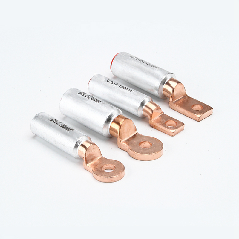
If you frequently work with copper lugs, mechanical terminals, wiring terminals, distribution panels, switchgear, electrical fittings, and similar products, this article is worth bookmarking.
Simply put, an installation torque chart is a reference guide for “how tight to tighten a screw.”
Its purpose is to tell you: for a specific size of screw or bolt, what torque value should be applied during installation.
There are generally two common units:
N·m (Newton-meters) and lbf·in (pounds-force-inches)
In electrical connection products, installation torque tables are commonly found in:
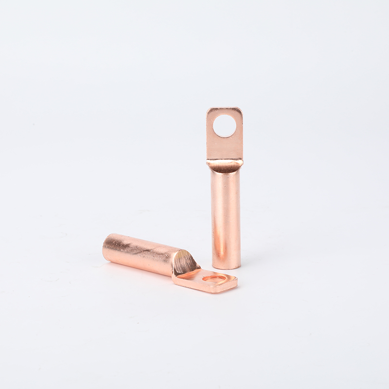
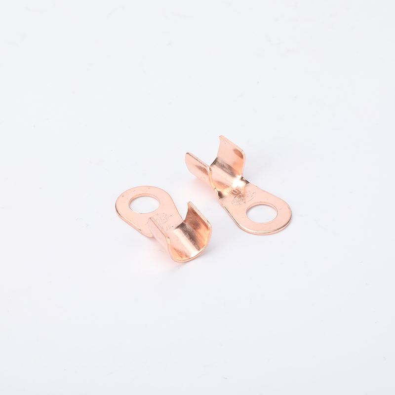
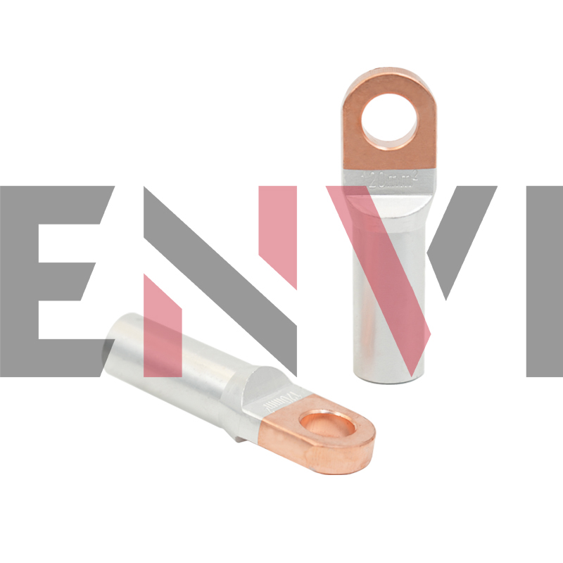
Mechanical lugs, branch connectors, copper-to-aluminum transition terminals, cable terminals, circuit breaker terminals, and wiring points in power distribution equipment.
You may have seen similar specifications in product documentation:
M6 screw: 6–8 N·m, M8 screw: 10–20 N·m, M10 screw: 25–40 N·m, and so on. Many people treat these as “reference values,” assuming that “close enough” is acceptable. However, these are not merely “informational” parameters; they are critical installation data that directly affect the reliability of the connection.
This is one of the most common misconceptions on-site.
Many people assume: “The tighter, the more secure; the more secure, the safer.” It sounds reasonable, but in electrical connections, this does not hold true. This is because the essence of a terminal connection is not simply “tightening the screw,” but rather achieving stable, sustained, and uniform contact pressure. Only when this pressure is appropriate can a reliable connection be formed between the conductor and the terminal.
What happens if the torque is too low?
The conductor is not pressed firmly enough, resulting in insufficient contact area and increased contact resistance. This causes localized heating when energized and makes the connection more prone to loosening during long-term operation.
Ultimately, this may lead to: terminal overheating, joint oxidation, screw loosening, insulation carbonization, and in severe cases, even burning.
However, excessive torque is equally dangerous.
This is because over-tightening can lead to: stripped threads, damaged screws, deformation of the terminal body, crushing of the aluminum conductor, uneven stress distribution across multi-strand copper wires, long-term stress concentration, and, ironically, increased likelihood of loosening over time.
The following scenarios are particularly prone to “over-tightening”:
Aluminum conductor connections, copper-aluminum transition connections, mechanical screw-type crimp terminals, and multi-strand flexible conductor wiring
Therefore, a truly reliable installation does not rely on “feel,” but on: the correct installation torque.
When terminal overheating occurs on-site, many people’s first reaction is usually: Is the material subpar? Is the copper content insufficient? Is the current too high? Are the terminals too thin? Is the workmanship poor? These could certainly be causes. However, a very common—and often overlooked—cause is actually incorrect installation torque.
A typical failure sequence often unfolds like this:
Insufficient torque → Conductor not securely clamped → Increased contact resistance → Localized temperature rise during operation → Thermal expansion and contraction + equipment vibration → Further loosening of the screw → Deteriorating contact → Increasing heat generation → Ultimately, burnout and failure.
This is why many connections work fine immediately after installation but start to overheat after some time. It’s not that they “suddenly broke down”; rather, the seeds of the problem were sown the moment they were installed.
Consult the equipment manual: Product manuals for terminal blocks, circuit breakers, relays, junction boxes, and similar products typically include a section labeled “Terminal Torque.”
Check the terminal surface or housing: Some brands (such as Phoenix Contact, Weidmüller, and Siemens) have the torque value directly stamped on the side of the terminal.
Refer to General Standards: If no specific value is provided, follow the recommended values in standards such as IEC 60947, UL 486E, or GB/T 14048. Common references are as follows: The table below lists the recommended torque values for bolts of different specifications. Unit: Newton-meter (N·m)
| Bolt Size (Metric) | Common Strength Grade | Recommended Torque Range (N·m) | Application Notes / Typical Scenarios |
| M6 | 4.8 / 5.8 | 5 – 8 | Small terminals, instrument mounting, control panel faces, lightweight cable ties |
| M8 | 4.8 / 8.8 | 10 – 20 | Small clamps, outdoor terminal boxes, surge arrester lead connections |
| M10 | 8.8 | 25 – 40 | Grounding clamps, low-voltage clamps, small disconnect switch connections |
| M12 | 8.8 | 50 – 70 | Medium clamps, suspension clamp secondary bolts, distribution transformer wiring |
| M16 | 8.8 | 150 – 200 | Tension clamps, connection fittings, main bolts for equipment clamps |
| M20 | 8.8 | 300 – 400 | Large tension clamps, rigid busbar fittings, critical structural connections |
| M24 | 8.8 | 500 – 600 | High-tension fittings, substation heavy equipment connections |
| M30 | 8.8 | 900 – 1100 | Heavy-duty fittings for critical sections like UHV lines and long spans |
Adjustable torque screwdriver: Used for small screws M3.5 and below, providing precise control.
Preset torque wrenches: For large terminals of M4 and above; feature an audible click indicator.
Digital torque meters: Suitable for laboratory use or high-precision applications.
Do not use ordinary screwdrivers or wrenches based on feel alone—human “feel” can result in errors exceeding ±50%.
Set the torque tool to the required value (e.g., 6 N·m).
Clean the contact surfaces of the wire and terminal (oxidation and dust can alter the actual clamping force).
Insert the wire fully into the terminal hole; ensure no copper strands are exposed.
Rotate the tool slowly and steadily until the set torque is reached (until you hear a “click” or the tool slips).
Do not apply additional force: Stop immediately upon reaching the torque to avoid over-tightening.
Multi-strand flexible wire + terminal block: It is recommended to use cold-pressed terminals (such as tubular terminals); otherwise, the flexible wire may deform under pressure, resulting in reduced actual clamping force despite the same torque value, which can lead to loosening.
Thermal cycling environments (such as heating equipment or outdoor enclosures): After initial installation, it is recommended to power on and run the system until thermal stabilization is achieved, then power off and retighten once according to the torque value (retightening in the hot state).
With spring washers or anti-loosening washers: The torque value is typically the same as without washers, but operate at a slightly slower speed to ensure the washers are fully compressed.
A torque wrench is not merely an optional reference but a core parameter for preventing terminal screw loosening.
As long as you follow these three steps:
Consult the table (find the correct value)
Use the right tool (torque screwdriver or wrench)
Follow procedures (clean, tighten slowly, and avoid re-tightening)
you can significantly reduce the failure rate caused by loose terminals. In industrial settings, distribution panels, charging stations, and servo drive wiring, this has become a standard operating procedure.
With extensive experience, excellent craftsmanship, and superior customer service, we meet various technical requirements to satisfy our customers and have gained widespread
 Optimized by Seraphinite Accelerator