Quick answer
Match the lug to the conductor first, then to the terminal stud. Copper conductor takes a copper lug; aluminium conductor takes an aluminium or a bimetallic (Cu-Al) lug; anything that joins copper to aluminium at a terminal takes a bimetallic lug. After that, confirm three numbers — conductor cross-section, stud hole diameter and palm width — and verify the product against IEC 61238-1 or GB/T 14315 before you approve the batch.
Most cable failures in LV and MV installations do not start in the cable. They start at the termination, where two different metals, two different thermal expansion rates and one under-torqued bolt meet.
A 400 A feeder can be specified, installed and load-tested perfectly and still fail inside three years, because someone picked a lug from a catalogue by cross-section alone. The specification that actually decides whether a joint survives twenty years of thermal cycling is a combination of conductor material, plating, barrel geometry, stud size and installation method. This guide walks through each of those decisions in the order a design engineer or a procurement team should make them, so the lug on the drawing is the lug that performs in the field.
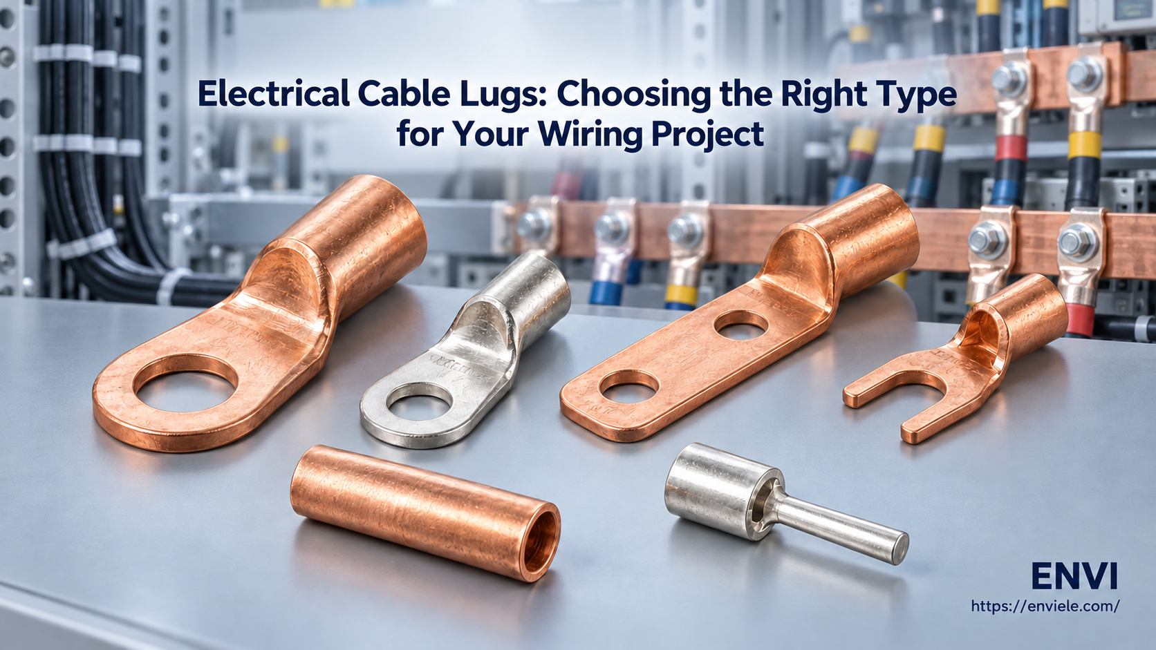
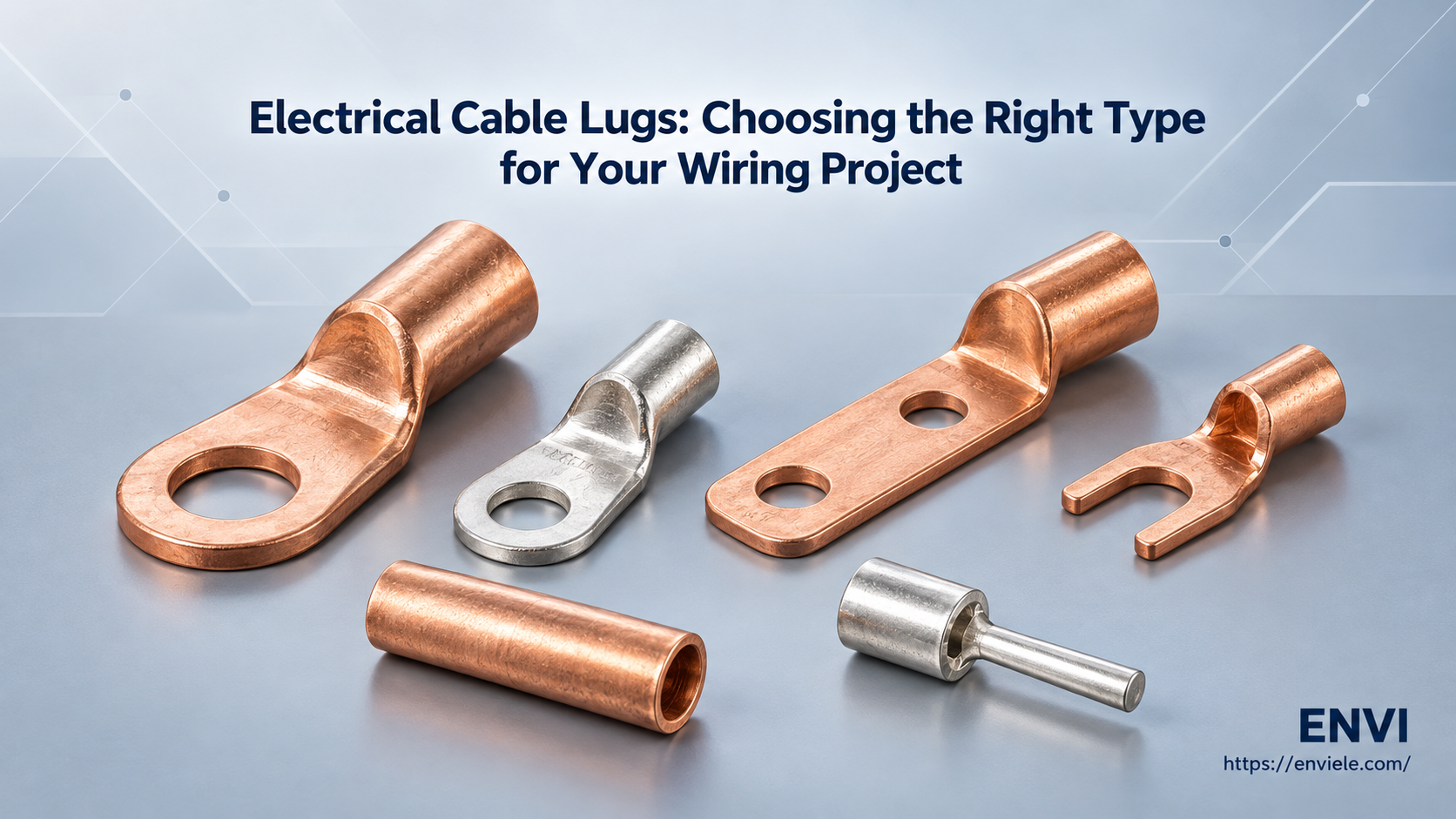
An electrical cable lug is a compression or mechanical terminal that converts a bare conductor into a bolted, low-resistance connection. It has three functional zones: a barrel that receives the conductor and is crimped or screwed onto it, a palm (also called the tongue) that carries the current into the equipment terminal, and a bolt hole that fixes the assembly to a busbar, breaker, transformer bushing or earth bar.
The lug is doing two jobs at once, and both have to hold. Mechanically, it must grip the stranded conductor tightly enough that tensile load and vibration never work the strands loose. Electrically, it must present a contact resistance low enough that the joint does not become the hottest point on the circuit. A well-made crimped joint typically reaches a resistance at or below that of an equal length of the conductor itself — which is exactly what the heat-cycle tests in IEC 61238-1 are designed to prove.
That dual role explains why lug quality is not judged by appearance. Two lugs can look identical in a photograph and differ by a full millimetre of barrel wall thickness, half a millimetre of plating, and an annealing step that decides whether the copper cracks when you crimp it in January. If you are still mapping the family tree of these parts, our overview of cable lug types covers the shapes and naming conventions before you get into materials.
Four material families cover almost every industrial project. The differences that matter commercially are conductivity, weight, corrosion behaviour and how each metal behaves when it is joined to a different metal.
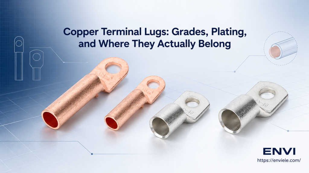
Copper is the default for a reason: about 58 MS/m conductivity (100 % IACS), excellent ductility, and a contact behaviour that stays stable under thermal cycling. Most Chinese production uses T2 copper per GB/T 5231, equivalent in practice to C11000 ETP copper, with a minimum copper content of 99.90 %. The trace oxygen in ETP copper is what makes it machine well; oxygen-free grades are reserved for vacuum or hydrogen-rich environments. A 99.9 % pure copper lug also crimps without cracking at the seam, which matters more than the purity figure itself.
Typical industrial copper lugs — tubular, ring, double-hole — are drawn from seamless tube or formed and brazed. The seamless version removes the seam as a possible crack path, which is why heavy-duty and high-vibration specifications increasingly call for it. Our DT copper terminal cable lugs are a standard reference point for this construction.
Aluminium delivers about 35 MS/m, roughly 61 % of copper, at a fraction of the weight and cost. On overhead lines and long aluminium feeder runs that trade-off is decisive: you accept a larger lug and a larger conductor for the same ampacity in exchange for lower mass on the structure and lower material cost. The engineering penalty is the surface oxide. Aluminium oxide forms in seconds, is electrically insulating, and must be broken mechanically by the crimp and protected afterwards with jointing compound. Aluminium also creeps under sustained bolt pressure, so mechanical aluminium lugs need re-torque schedules that copper lugs do not.
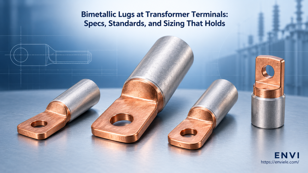
A bimetallic lug exists to solve one specific problem: an aluminium cable arriving at a copper terminal. Bolting the two metals directly together creates a galvanic cell, because aluminium sits far below copper in the galvanic series and becomes the anode. Add moisture and the aluminium side corrodes preferentially, contact resistance climbs, and the joint heats. On top of the electrochemistry, copper expands at roughly 17 × 10-6/K while aluminium expands at about 23 × 10-6/K, so every load cycle works the bolted joint loose.
A friction-welded Cu-Al lug removes both mechanisms from the field: the copper-to-aluminium transition happens inside the factory under pressure and temperature, producing a metallurgical bond that is then never opened again. What the installer sees is a copper palm for the copper terminal and an aluminium barrel for the aluminium conductor. If that architecture is new to you, our comparison of copper vs aluminium lugs sets out the six differences that drive the decision, and the DTL bimetallic copper-aluminium cable lug shows the standard DTL geometry.
Insulated lugs (the SV, RV and BV families) carry a moulded PVC or nylon sleeve over the barrel and palm shoulder. The sleeve is not decoration: it provides touch protection at the joint, strain relief where a fine-strand flexible conductor leaves the crimp, and a colour code that lets a panel builder verify wire gauge at a glance. Non-insulated lugs are the right choice wherever the joint sits inside a lug cover, heat-shrink boot or insulating shroud — adding a second insulation layer there only makes the assembly bulkier and harder to seal.
| Property | Copper | Aluminium | Bimetallic (Cu-Al) |
|---|---|---|---|
| Conductivity | ~58 MS/m (100 % IACS) | ~35 MS/m (61 % IACS) | Copper side 100 %, Al side 61 % |
| Weight vs copper | Reference | ~30 % lighter | Between the two |
| Oxide behaviour | Conductive oxide, self-limiting | Insulating oxide, needs compound | Al side needs compound |
| Direct Cu joint | Yes | No — galvanic corrosion | Yes — by design |
| Best fit | Panels, busbars, breakers | Overhead, long Al feeders | Transformer, Al cable to Cu bar |
Conductivity values are typical for annealed T2/C11000 copper and 1350-series aluminium at 20 °C. Confirm the actual figures on the supplier’s test report rather than on a datasheet cover page.
Not sure which material fits your project?
Send us the conductor material, cross-section and terminal stud size. ENVI’s engineering team will confirm the lug type and the crimp die in one reply — no catalogue trawling required.
Once the material family is settled, four specification parameters decide whether the part actually fits. Get any one of them wrong and the lug either will not enter the terminal or will not carry the current.
This is the parameter that cannot be compromised. Copper conductor, copper lug. Aluminium conductor, aluminium or bimetallic lug. Aluminium conductor into a copper terminal, bimetallic lug. Never an aluminium lug on a copper conductor — the aluminium barrel work-hardens and the joint loosens as the copper expands against it.
The barrel must match the nominal conductor cross-section, not the nearest available size. A lug rated for 95 mm² used on 70 mm² cable leaves voids inside the barrel that no amount of crimping force will close. Current rating is a separate calculation that depends on installation conditions, so treat catalogue ampacity as a starting point and apply the derating factors from your local wiring code. The table below gives indicative values for single-core copper cable in free air at 30 °C ambient; enclosed, grouped or high-ambient installations will be lower.
| Conductor (mm²) | Barrel ID (mm, approx.) | Typical stud | Indicative ampacity (A) |
|---|---|---|---|
| 16 | 5.5–6.0 | M6 | ~75 |
| 35 | 8.0–8.5 | M8 | ~135 |
| 95 | 13.5–14.0 | M10 | ~250 |
| 240 | 21.0–21.5 | M12 | ~480 |
| 400 | 27.0–28.0 | M12 / M16 | ~680 |
The bolt hole must clear the stud with enough margin for a washer and for thermal expansion, but not so much that the palm shifts under load. As a working rule the hole runs 0.5–1.0 mm larger than the nominal stud diameter: 8.5 mm for M8, 10.5 mm for M10, 13 mm for M12, 17 mm for M16. Palm width is the parameter that quietly causes rework, because a standard palm will not fit between the phase barriers of a compact breaker. If your terminal pitch is tight, a narrow-tongue variant solves it without changing the conductor rating.
Standards do not make a lug good, but they define what a supplier must prove. For power cable terminations the reference documents are IEC 61238-1 (compression and mechanical connectors for power cables up to 30 kV) and its Chinese counterpart GB/T 14315 for compression-type copper and aluminium terminal lugs. Dimensional conventions come from DIN 46235 for copper compression lugs and JIS C 2805 for the Japanese R/S series; North American projects usually cite UL 486A-486B. A supplier claiming compliance should be able to send a third-party report naming the standard, the test laboratory and the class achieved.
The full range of barrel styles, palm shapes and stud configurations lives in our cable lug product range, where each series is listed with its cross-section band and stud options.
Free selection aid: lug sizing quick reference
Save the table above as a one-page checklist for your installers. The five fields that cause 90 % of wrong-part orders are conductor material, cross-section, barrel ID, stud hole and palm width — capture all five on the requisition and the error rate drops to near zero.
The same 95 mm² conductor may need four different lugs depending on where it terminates. This is the step where project experience beats catalogue logic.
| Application | Recommended form | Why |
|---|---|---|
| Panel & busbar | Tinned single or double-hole tubular | Two-hole resists rotation; tin blocks tarnish |
| Transformer terminal | Bimetallic DTL / DTLS | Al cable meets Cu bushing stud |
| Solar DC / string | Tinned copper, sealed with heat-shrink | UV, humidity and daily thermal cycling |
| Control panel / small gauge | Insulated ring, spade or pin terminal | Touch protection and colour-coded gauge |
| High-vibration equipment | Seamless barrel, long barrel, double crimp | Fatigue resistance at the crimp transition |
| Field repair, no press | Mechanical shear-bolt lug | Wrench only, single torque value, no die set |
Two installation principles apply regardless of the family you choose. First, use the die that matches the lug series, not the one that happens to fit the press — a hexagonal die closed on the wrong barrel produces a joint that looks right and tests wrong. Second, seal the entry. Heat-shrink with adhesive lining, or a gel-filled lug cover, keeps moisture out of the strand interstices, which is where corrosion starts long before it reaches the palm.
Copper lugs conduct about 58 MS/m against roughly 35 MS/m for aluminium, so an aluminium lug must be physically larger for the same current. Copper is ductile and crimps without cracking; aluminium is lighter and cheaper but forms an insulating oxide that requires jointing compound and a wire brush. Crucially, the two metals cannot be bolted together directly without galvanic corrosion, which is why a bimetallic lug is used at the interface.
Whenever an aluminium conductor terminates on a copper or brass surface and the joint will be exposed to moisture, salt or sustained load cycling. Transformer bushings, outdoor metering cabinets, pole-mounted switchgear and the copper bar side of an AC distribution board are the classic cases. If both sides of the joint are the same metal, a bimetallic lug adds cost without adding value.
IEC 61238-1 defines the type tests a compression or mechanical connector must survive: mechanical tensile load, heat cycling under current, and short-circuit withstand, with resistance measured before, during and after. A lug described as “tested to IEC 61238-1” has been through that sequence at an accredited laboratory. Without a named class and a test report, the claim is marketing rather than compliance.
Read three numbers off the drawing: nominal conductor cross-section, terminal stud diameter and available palm width. The lug’s barrel must match the cross-section band exactly, the bolt hole should run about 0.5–1.0 mm over the stud diameter, and the palm must clear the phase barriers. Current rating follows from the installation conditions, not from the lug alone.
Choosing a cable lug is a five-decision sequence, and the order matters: conductor material, cross-section, stud and palm geometry, standard compliance, then application and installation method. Teams that specify in that order stop buying the wrong part, and they stop discovering it on site.
The remaining variable is the supplier. Barrel wall thickness, plating thickness and copper grade are invisible in a photograph but decide whether the joint is still at 20 °C over ambient in year fifteen. That is the difference between a lug that meets a drawing and a lug that meets a standard.
ENVI — cable lug manufacturing since 1995
Copper, aluminium and friction-welded bimetallic lugs, produced in-house from T2 copper to GB/T 5231 and tested to IEC 61238-1 and GB/T 14315. Send your drawing for a same-week quotation, or request free samples for your next pilot batch.
Copper vs aluminium lugs: 6 key differences
Your guide to selecting the correct electrical cable lug size
10 common mistakes when crimping cable lugs
Top 6 cable lug materials explained

With extensive experience, excellent craftsmanship, and superior customer service, we meet various technical requirements to satisfy our customers and have gained widespread